The RC Interceptor
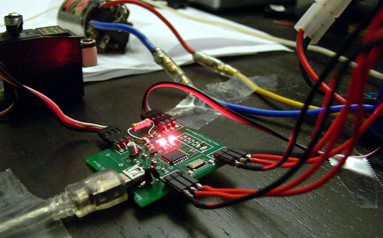
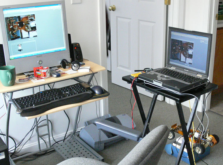
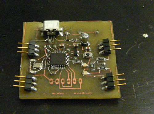
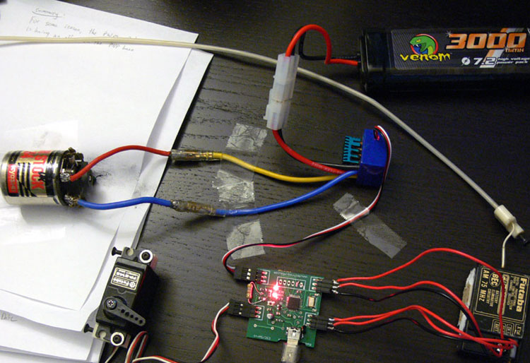
The RC Interceptor is a circuit board that is capable of controlling an RC vehicle from the USB port on a computer. It was programmed to act like a virtual serial device and works across Windows, Linux, and Macintosh platforms. The unique thing about this board compared to other devices capable of controlling servos or motors is that when not plugged into a USB port, it will allow signals to pass from the radio to associated components uninterrupted. When the USB port is plugged in, the board will completely kill the signals coming from the radio and allow the computer to take full control.
There were a few goals that I had with this project that I will overview, then explain them in detail. The first major goal was to create a means of allowing me to control my RC Car easily through USB. The second was to become familiar with the AT series of Atmel micro-controllers. The third was to try and focus on circuit board size and layout.
Controlling an RC Car Through USB
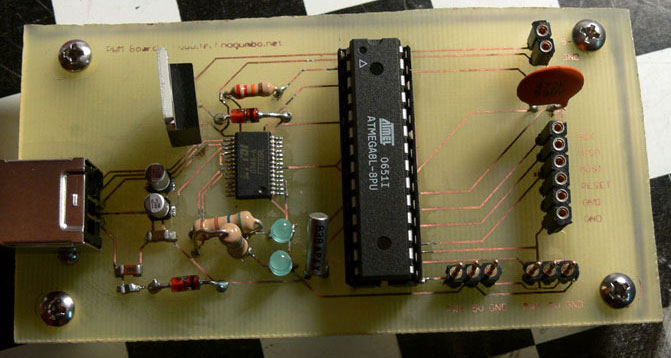
I have been working on this over-all issue since way back in early 2008. One of the first circuit boards I made by hand was based on an Atmel Atmega8-L. Back in October 2008, this board had some shorts and had a little fire while I was stress testing it on my RC Car in August 2008.Not understanding the electronics of an RC system fully, this led me down two paths. One of thinking I could make my own ESC (Electronic Speed Controller) and another worried about isolating computer electronics from RC system electronics completely.
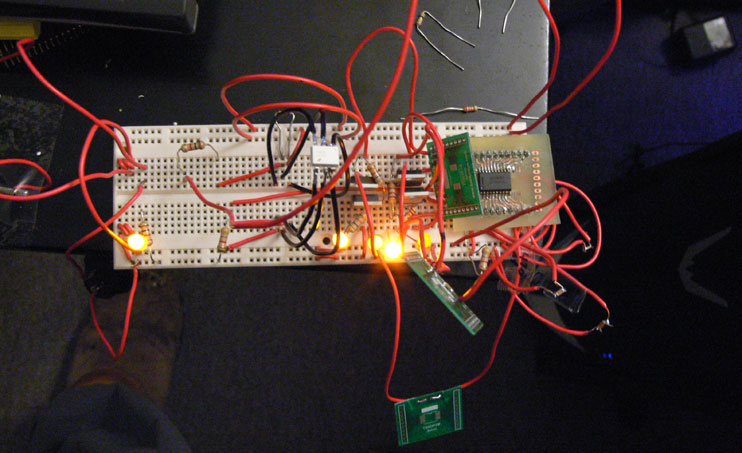
The issue with isolation is what led to my experimenting with optocouplers and eventually writing a tutorial about the popular 4N25.
The issue of making my own speed controller led me down a path of doing tons of research on high and low pass filters as well as experimenting with bridge drivers and a few types of MOSFETS.
After experimenting with both of these, it hit me that the real solution to this is to make a device that could easily integrate into existing RC systems while maintaining their full functionality. I started concept work and research on what would end up as this project in May, 2009.
Becoming Familiar with the AT Series of Micro-Controllers
I have always had a keen interest in USB devices because they are so versatile. My first microcontrollers used the popular FTDI RS232RL chip to handle usb to serial communication. When I found out that Atmel made a microcontroller that could do USB by itself I wanted to learn how to use it. This not only reduces circuit board cost, but also reduces circuit board size. I also wanted another excuse to become more familiar with the guts of implementing USB devices and drivers.I also read that you could program this chip via usb directly from the factory because it comes with a bootloader. The hand-made parallel programmer that I use with the Atmega series of chips just wasn't doing it for me anymore.
A blessing that I found early on in this project was the teensy development board from PJRC. It uses the AT90USB162, which is the same micro-controller that I had decided to use for this project. The code samples and electric design of the teensy provided many great learning opportunities. It also provided invaluable examples of what electrical signals coming from this micro-controller are supposed to look like running properly during the hardware debugging stage.
Circuit Board Size and Layout
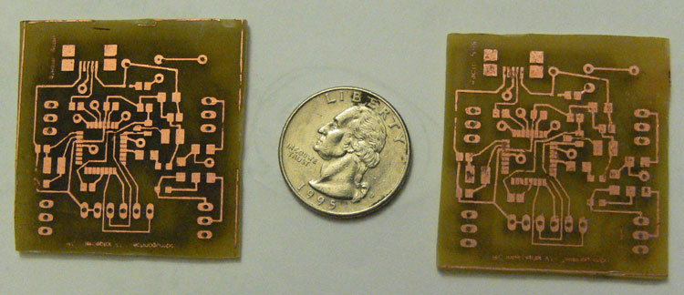
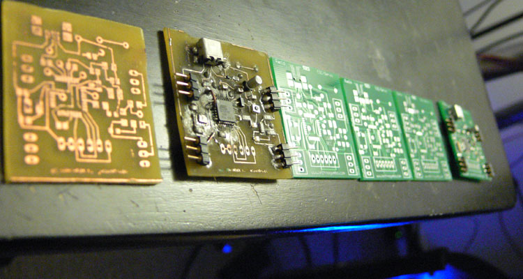
This was the first circuit board project that I tried to make so other people could potentially use it. I went through roughly six board layouts before choosing a layout that I tried to initially make by hand. In the past, I have been using 1206 size surface mount parts because I hand manufacture my electronics, but for this project I decided to go with 805 and also some even smaller diode packages.I was able to successfully hand manufacture the dual layer motion sensing telegraph board for Arduino at work, so I tried to hand manufacture the prototype for this project as well. I did a pretty good job considering how small it is. My first board may have worked if I had the correct clock, but I didn't. I initially built this board with a 16Mhz clock. If you carefully read the documentation, you'll see that in order to get the factory boot-loader to work so you can program the AT90USB162 through USB, the board must be running at 8Mhz.
Realizing that this project was just too small to hand manufacture, I did some research on how to have a quick turn fabrication house make a batch of printed circuit boards. I shopped around, but finally settled on Batch PCB. I had four boards made, only one of which I have assembled. After assembly I realized that the current design (at time of writing) still has lingering design flaws that will have to be resolved in another run.
Unexpected Learning Opportunities
Once I finally got one of the new boards assembled, I had a lot of trouble getting it to operate in a stable fashion. I got it to run long enough to load code on it, but it would mysteriously not startup correctly and operate very intermittently. My intuition told me this had to be a clock issue.I got a hold of an old oscilloscope and worked with it until I got really good at understanding how to use it. Looking at the 8Mhz waveform and comparing that with the AT90USB162 documentation concerning the chips startup cycle, I could see that it looked like it was getting stuck trying to jar the clock source into stable operation. Sometimes it could get it going, and sometimes it could not. I could do mysterious things like short certain parts of the board and it would sometimes jar the board into operation.
This led me down yet another rabbit hole of understanding how to get a high speed clock to operate in a stable manner. After some research, I purchased "High-Speed Digital Design, A Handbook of Black Magic" by Howard W. Johnson and Martin Graham. I was able to read and understand this in it's entirety in a little under two weeks by reading a chapter a day with more on the weekends. I also found an Intel specification on passing FCC testing for USB devices with was helpful at all.
After reading that book, I was concerned that due to my over-all board layout it may not work at all. I went from knowing not much about PCB layout, to knowing a lot. I got lucky for the prototype and connecting the USB mini-b shield to ground has proven to allow consistent stable operation.
However, the story doesn't end there. After I was able to fix the clock issue, I found out that the control signals coming from my board were not able to control an ESC and servo. This led to a lot of looking at PWM waveforms on the oscilloscope and comparing the RC Interceptor waveforms to the radio's to teensy's. It turned out that the transistors I was using to kill the radio pwm waveform were not working like I had wanted them to. After a lot of testing, and cannibalizing the hand-made version, I was able to add some high value resistors to the RC Interceptor prototype and have it finally working 100%.
Im happy to say that the rough prototype board has already survived a few RC car crashes as well as disassembled testing, and several hours of running on USB power.
Comments

Hi ardvark,
I never ended up making any more of these due to the fact that there are several multi-channel controllers which are likely better products than this would have been.
Thanks for your interest. I hope you have a great holiday weekend!

Hi there, has anything become of this project?

Im sorry uditha, Ive never made a production run of these. You may want to check out FIRST robots, as I think they have several devices like this with multiple channels.

where can i buy usb rc intercepter

I have been searching for exactly this sort of device this should be in every hobby and rc shop across the world when can i buy one .

Hi
I like one to :) its so cool have a 10" ATOM LAPTOP WITH A BROKEN SCREEN that can controle the car..
My email is cblood_andreas@hotmail.com
Hope to hear from you
Andreas

I just added a poll to this page at the top left under the site menu. Please vote as it will help me determine if I should make this a product others can purchase.

Where can I get The RC Interceptor USB device ? SAILOR2S@hotmail.com

Jordo, Please shoot me an email at palen1c at gmail dot com or use the chat thingy on the main page of technogumbo.com to work out the details with me. I would love to build you one. Thanks for your interest!

I would like to purchase one. is there a chance that you would build an interceptor for me to purchase? and good job very impressive.

There is no spec shet. What type of information are you looking for? It works with BEC at 5V. I have tested it with a Futaba and LRP speed controller.

Where can we download the specs?!?
Comments are currently disabled.
