
Fixing PNP Transistor Capacitance Issues
Sun, 11 Oct 2009 21:55:04 EST
The first issue in the initial design of this circuit is that the RC Controller signal was not being killed all the way. So whenever USB was connected, you would have the RC Controller signal and USB signal interfering with each other. This was simply an issue of not reading the PNP transistor datasheet correctly. I made the circuit based on saturation parameters NOT start of turn on parameters. Saturation is when a transistor is pretty close to all the way on. However, when it starts to turn on, some of the signal will slip through the collector and emitter.
In a PNP transistor, the way I fixed this was by adding a much larger resistor in series with the base of the device in relation to ground. This limits the current that can get to the transistor.
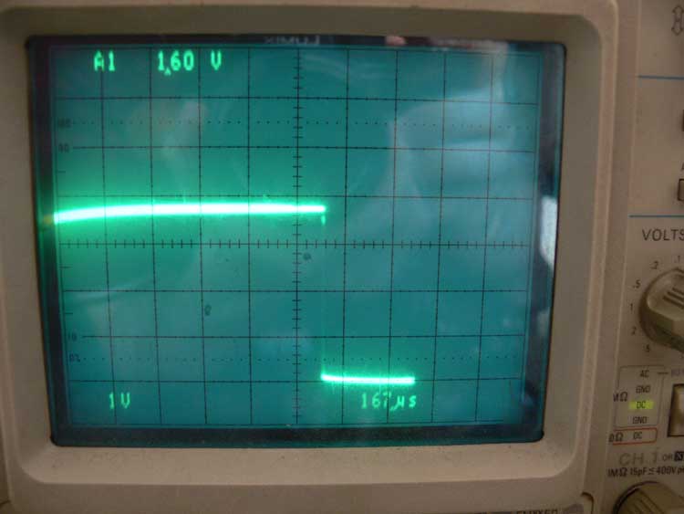
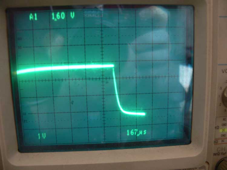
The second issue I think was a matter of capacitance. Every electrical circuit has some sort of minimal capacitance which can be minimized based on component selection, biasing, and circuit board layout. The PNP transistor I was using has a pretty small capacitance, but as you can see based on the oscilloscope images, it was totally screwing up the turn off of my pulse width modulation waveform.
In order to fix a falling capacitance issue, you need to bias the output towards ground. So in order to fix the output PWM waveform I added a large value resistor connected to ground to the output PWM line. By doing this, it allows a small hole in which that capacitance can escape quickly without effecting your final waveform! The result is that I can finally move on to stress testing this thing during the coming week.

Charles Palen has been involved in the technology sector for several years. His formal education focused on Enterprise Database Administration. He currently works as the principal software architect and manager at Transcending Digital where he can be hired for your next contract project. Charles is a full stack developer who has been on the front lines of small business and enterprise for over 10 years. Charles current expertise covers the areas of human pose estimation models, diffusion models, agentic workflows, .NET, Java, Python, Node.js, Javascript, HTML, and CSS. Charles created Technogumbo in 2008 as a way to share lessons learned while making original products.
Comments
No one has posted any comments yet, be the first
Comments are currently disabled.
