Sat, 12 Mar 2011 23:38:42 EST
Charlieplexing is a relatively recent technique used in electrical engineering with microcontrollers in order to fully take advantage of a microcontrollers multi pin state properties. It basically allows you to control a lot more devices from a lot less pins. I'm embarrassed to admit that I never knew about charlieplexing until recently studying how it works and making my own implementation. A recent article on
Hack-a-day about a charlieplexing layout tip is what originally alerted me to the technique. The
Wikipedia article on charlieplexing does it more justice than I could ever explain. The first project I took on using the technique was getting six LEDs to be controlled from only three pins following the simple diagram in the Wikipedia article.
Following the techniques in the Wikipedia article you can get 2x the IO pins to control whatever you want. So basically you can control six on/off low amperage type devices only using three pins.
This worked great so I moved onto seven segment displays following an
Instructables article about Charlieplexing Seven Segment Displays. After spending a week and a half of my spare time examining the example code with the exact same hardware and translating it to a AT90USB162 microcontroller, I'm certain there is something wrong with the firmware code posted in the Instructables article. I had to slowly re-write the firmware myself to get the example to work after examining my wiring several times. I also included protective resistors on the transistor bases and common annode on the seven segment display.

After knowing the basics, the Instructables article proposes an exciting technique because it introduces a way to control WAY more than 2x the number of devices by including additional boolean logic devices on one additional line; transistors. Seven segment displays use seven IO lines as well as a decimal point, which makes eight. The Instructables article includes a 9th line which in combination with transistors basically allows you to control 8 x 7...56 (they only use 8x6 in the example) lines using fast timing techniques.
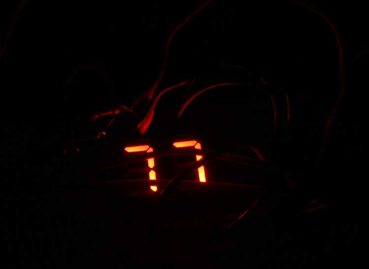
The basic idea is that every single line in the full array is turned on and off in sequential order, but it is preformed so fast that it looks to the human eye like every single line is on at the same time. In my simple example I'm only doing this with two seven segment displays running at 16Mhz but I can clearly see how to scale the example.
This is a really fundamental technique in working with microcontrollers that I am very excited to have learned about. Thanks to the generous authors on Hack-a-day, Wikipedia, and Instructables.
Charles Palen has been involved in the technology sector for several years. His formal education focused on Enterprise Database Administration. He currently works as the principal software architect and manager at
Transcending Digital where he can be hired for your next contract project. Charles is a full stack developer who has been on the front lines of small business and enterprise for over 10 years. Charles current expertise covers the areas of human pose estimation models, diffusion models, agentic workflows, .NET, Java, Python, Node.js, Javascript, HTML, and CSS. Charles created
Technogumbo in 2008 as a way to share lessons learned while making original products.
Comments are currently disabled.