Mistakes in Hand Circuit Board Fabrication
Mon, 03 Aug 2009 07:00:00 EST
The tough part about making a circuit board with surface mount technology is that there isnt much room for error in any part of the process. In working with the AT90USB162, I have been
making a concept product for RC systems that incorporates the smallest electronic packages I have ever used. The boards are also double sided which means both sides must be in perfect alignment.
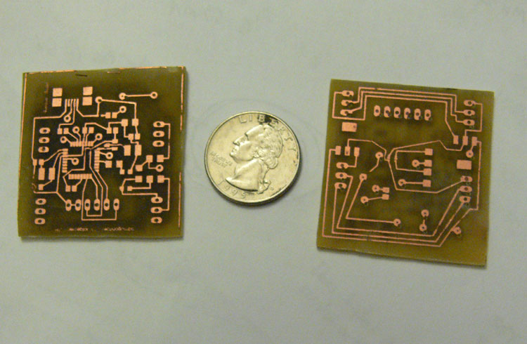
This is the first time I have used vias as well. I hand make boards using the toner transfer method with an iron and etch them myself, then hand drill all the pin holes and vias.
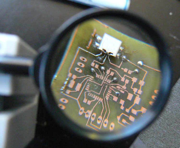
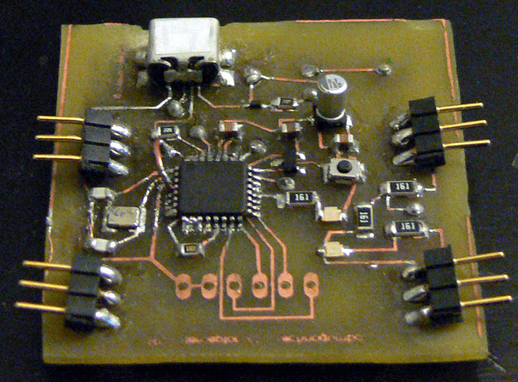
This time around seeing as the design is so small I found that despite making two identical boards, the leads for the AT90USB162 were all fused together, so I had to spend quite a bit of time with a blade separating them before being able to mount parts. The vias also caused a bit of a problem. In particular I placed a via directly underneath the AT90USB162. When hand making a board, there is no way you can make a via that is flat enough to sit underneath such a small IC. I ended up accidentally ripping that one off the board as well as its associated pin and had to use a jumper wire for it. In the image of the top part of the assembled board you can see the jumper wire in the top left of the IC. Its the weird arch.
Without knowing exactly what I was getting into I also used a diode array that was in a BAT30 package..so thats six leads that need to be soldered. A BAT30 is so small that you could probably fit 10 to 15 of them on your thumbnail. I managed to solder it just fine, but the leads for the design were all fused together from using the iron on method of pattern transfer. I also managed to loose the diode array in the carpet and miraculously found it prior to vacuuming the carpet.
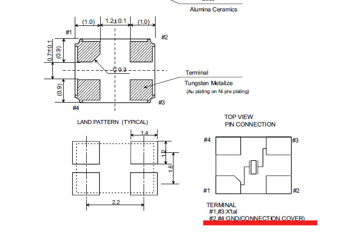
After several hours of assembly and careful verification of every pin (probably 12 to 16 hours total), I plugged the board in to find that as expected it didnt work. (Complex things never work the first time unless you get very lucky) Im quite certain that I mounted the clock source wrong. I used a surface mount crystal (Digikey part number 644-1100-1-ND) that is 3.2mm x 2.5mm. I had no outline for this part in Eagle so I cleverly used two 1206 sized resistor pads stuck together. The 1206 package is 3.2mm x 1.6mm so its spacing is perfect. However, the clock came with four landing pads and based on the datasheet, I foolishly didnt make the connection that pads 2 and 4 were actually connected to the metallic cover. In my pad layout, I actually connected pads 1, 4 and 2,3. When I mounted the clock, I accidentally got solder on the super small metalic cover and guess what.....it caused a direct short between pins 1 and 3 rendering the clock and therefore the whole board useless. Awesome. I happen to have a 16Mhz resonator in my spare parts so I may see if I can get that to work.

Charles Palen has been involved in the technology sector for several years. His formal education focused on Enterprise Database Administration. He currently works as the principal software architect and manager at Transcending Digital where he can be hired for your next contract project. Charles is a full stack developer who has been on the front lines of small business and enterprise for over 10 years. Charles current expertise covers the areas of human pose estimation models, diffusion models, agentic workflows, .NET, Java, Python, Node.js, Javascript, HTML, and CSS. Charles created Technogumbo in 2008 as a way to share lessons learned while making original products.
Comments
No one has posted any comments yet, be the first
Comments are currently disabled.


