
Controlling Servos With the AT90USB162 or Teensy
Mon, 13 Jul 2009 07:32:10 EST
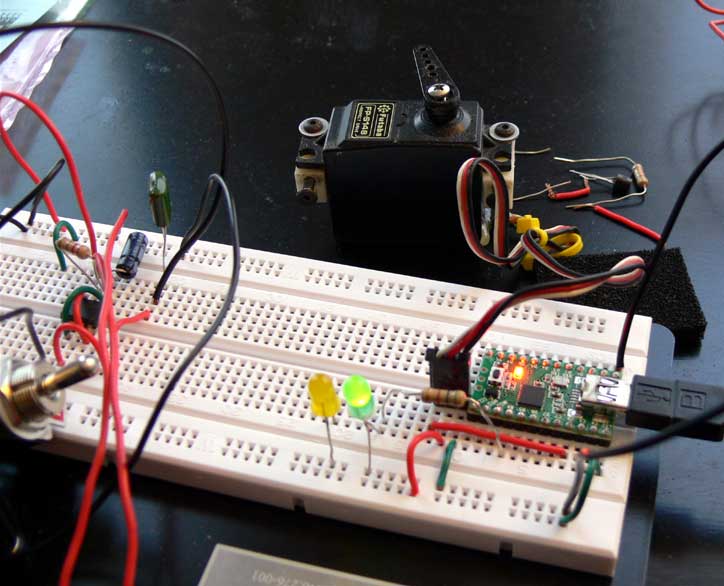
Let me elaborate. For controlling a servo, you must generate at PWM signal at 50Hz (50 times a second). You may have seen people talking about this as 20 milliseconds. You get 20ms by taking the 1000ms in one second and dividing by 50...get it? So in order to control the position of a servo you need your pulse width signal to be on for only 1 to 2ms of your full 20ms cycle.
From my understanding, if you look at the 8bit counter on the AT90USB162, you can only use 0xFF(decimal 255) or the OCR0A register for the TOP of the counter which also has a max value of 255. The formula for calculating the frequency of Fast PWM mode for the 8bit counter is as follows:
Frequency = Clock Speed / Prescaler * 256.
The Teensy has a fixed Clock speed of 16Mhz or 16,000,000. The highest Prescaler you can use is 1024. So, if we use the max prescaler...
16,000,000/ (1024 * 256) = about 61.03Hz.
You can get lower using PWM Phase Correct mode, but never hit 50Hz exact at a fixed 16Mhz clock speed; so the 8bit timer can not be used for controlling a servo!
I set up the 16bit counter to actually work for 50Hz so let me show you the settings I used below.
For the 16bit Counter/Timer (Im having it output on pin 23 or PC6) you can make TOP the value equal to the ICR1 register which is key. You can then cycle the on and off duration by changing the value of the OCR1A register. So the formula in the 16bit counter for setting PWM frequency in fast PWM mode is as follows (datasheet page 122).
Frequency = Clock Speed / Prescaler * (1 + TOP)
Lets plug in our values needed to get close to 50Hz. 16,000,000 / 8 * (1 + 40,000)
So Prescaler = 8, TOP = 40,000.
This actually works. If you vary the value of OCR1A between 2200 to 3800 youll get pretty close to the 1 to 2ms on time for the 20ms period in order to control the full range of the servo. My exact register settings for the C programming language using the AVRlibC library are below. I have the timer set to CLEAR on compare match, SET at TOP.
// Added by CDP 7/13/2009
// Cant use the 8 bit timer at 16Mhz to ever get a 50Hz PWM signal like a servo requires!
void pwm_init_two(void) {
// FAST PWM Mode 14
// Using Channel A on PC6 set COM1A1 --> Clear OCnA/OCnB/OCnC on compare match,set OCnA/OCnB/OCnC at TOP
TCCR1A = (1 << COM1A1) | (1 << WGM11);
// WGM11, WGM12 and WGM13 set PWM output mode 14 so ICR1 is top
TCCR1B = (1 << WGM12) | (1 << WGM13) | (1 << CS11); // <--- Prescaling by 8
// WGMn Bits must be set before ICR1
// Using ICR1 as TOP For 50Hz Output at max resolution set at 40,000
// 16,000,000 / 8 * 40001 = ~50hz
ICR1 = 40000;
// Setup PWM prior to setting the data direction
// Setup the pwm output pin an output - because only doing one just set the bit value
// Use OR in case other bits have been set in DDRB
DDRC |= (1 << PWM_OUTPUT_PIN);
// Set B4 as ouput so I can toggle it as output
DDRB |= (1 << PB4);
// Set OCRA1 to something - Servo is based on 1 - 2ms pulse if 40000 = 20ms pulse whats between 1 and 2 (2200 TO 3800)
OCR1A = 3400;
}

Charles Palen has been involved in the technology sector for several years. His formal education focused on Enterprise Database Administration. He currently works as the principal software architect and manager at Transcending Digital where he can be hired for your next contract project. Charles is a full stack developer who has been on the front lines of small business and enterprise for over 10 years. Charles current expertise covers the areas of human pose estimation models, diffusion models, agentic workflows, .NET, Java, Python, Node.js, Javascript, HTML, and CSS. Charles created Technogumbo in 2008 as a way to share lessons learned while making original products.
Comments
Günter

January 7, 2013 07:28 am
Ich bin GB.
rew
October 12, 2010 02:50 am
Hi,
It is not essential to get "exactly" 50Hz. Many ESCs work just great if you update their throttle setting at more than 50Hz. For example 300Hz works just fine. How's that for "not exactly"?!!!
Similarly, servos will not care if you do 40-60Hz. Some may due to their build overheat when you go significantly above 50Hz.
Comments are currently disabled.
